Build guides
Atalaia's props are built from off-the-shelf parts around one ESP32 board, with no custom circuit board. This page has the Field Box's pins and wiring diagrams and the guides for the Satellite, the I/O pod and the target addon, shortened; the full guides, with every check and the troubleshooting tables, are in the repository. To put the firmware on a board, download a ready-made release or build it yourself: the firmware guide explains both. The field controller has its own setup guide. The radio modem has its own modem guide.
Not sure what plugs into what? See how the parts talk to each other →
No box has been built from these guides, and the Field Box has no enclosure yet. There is only a bench build of the Field Box (loose wires), playing games. Its pins are checked automatically against the firmware, but every physical step (enclosure, power, runtime, radio range) is untested, and the photos of the other boxes will come with their first builds. If you build one, please tell us what you find.
Safety first
These rules hold for every build on this page, as for the Field Box.
- Never power a board without its LoRa antenna, not even from USB: transmitting into an open antenna port can destroy the radio's amplifier. Fit both antennas first and leave them on.
- One Li-ion cell in series only (1S, 3.0–4.2 V): protected cells, a fuse close to the cell and a diode against a cell put in the wrong way round. The board's battery socket and charger take one cell; a 2S pack destroys them. Check the polarity with a meter before every connection: small battery plugs have no standard polarity.
- Charge under supervision, never in a closed case, only between about 0 and 45 °C, and keep the cells in a fire-safe bag while you work, with the cells out of the box. Never use a cell that is dented, swollen, hot or below 2.5 V.
- 3.3 V signals only into the board: the LED ring is driven through a level shifter, and every I2C module must pull its lines up to 3.3 V, never 5 V.
- Never wire GPIO 5 or 46 (the radio's front end) nor GPIO 34 or 38–42 (the board's GPS connector).
- No game before the transmit-power check of the bring-up list: the firmware keeps the radio within the legal limit with an amplifier gain that has not been measured yet.
- Plastic, never metal (the radio must get out), weatherproof, in a bright colour with a "GAME PROP" label, and nothing that looks like an explosive device.
- BBs and paintballs will hit it. Keep the cells and boards away from the walls and out of the line of fire, put a phone's screen behind clear polycarbonate (never glass), and never place a box where players have to shoot at it, unless it is a target.
Field Box
The main prop, with team buttons, a keypad, a colour screen, an LED ring, an NFC reader and a speaker. Its build manual has the parts, the wiring diagrams, power and battery safety, the first flash and troubleshooting; the guides below refer to it for every step they share.
The first build, on the bench
The Field Box now exists off paper, but only as a bench build: the first board to run a whole game, with the screen, buttons and keypad on loose wires and no enclosure yet. It is not a finished product, nor a box built from the guides.


Pins
The firmware's defaults. Every board pin that is not in this table stays unconnected.
| What | GPIO |
|---|---|
| Team button 1 (the game's first team) | 4 |
| Team button 2 (the second team) | 48 |
| Team button 3, optional (the board's UART0 receive line) | 44 |
| Team button 4 (on the keypad expander) | PCF8574 P7 |
| Keypad, through the PCF8574 expander (address 0x20) | PCF8574 P0–P6 |
| LED ring data, through the 74AHCT125 level shifter | 35 |
| Screen MOSI (SPI) | 33 |
| Screen clock (SCK) | 47 |
| Screen chip select (CS; the board's battery-voltage pin, used as an output) | 1 |
| Screen data/command (DC) | 3 |
| Screen RESET and backlight: both to the 3V3 pin, no GPIO | 3V3 |
| I2C SDA, for the keypad expander, the NFC reader and the battery gauge (the board's own bus) | 17 |
| I2C SCL | 18 |
| Amplifier BCLK (optional) | 6 |
| Amplifier LRC | 15 |
| Amplifier DIN | 16 |
GPIO 1, 35 and 44 are board pins that the Field Box shares on purpose, each for this one use only: 1 is the board's battery-voltage input (the gauge reads the battery over I2C instead), 35 its white LED (it flickers faintly with the ring) and 44 UART0's receive line (the USB console is unaffected).
Wiring diagrams
Two drawings, generated from the repository's WireViz files: the signals with the 3.3 V logic power, and the battery, switch and 5 V rail. The board's pins are named by GPIO number only: find each one by the number printed next to its header pin. The labels (pins, wires, parts) stay in English in every language, as in the repository; if the text and a drawing disagree, the drawing wins.
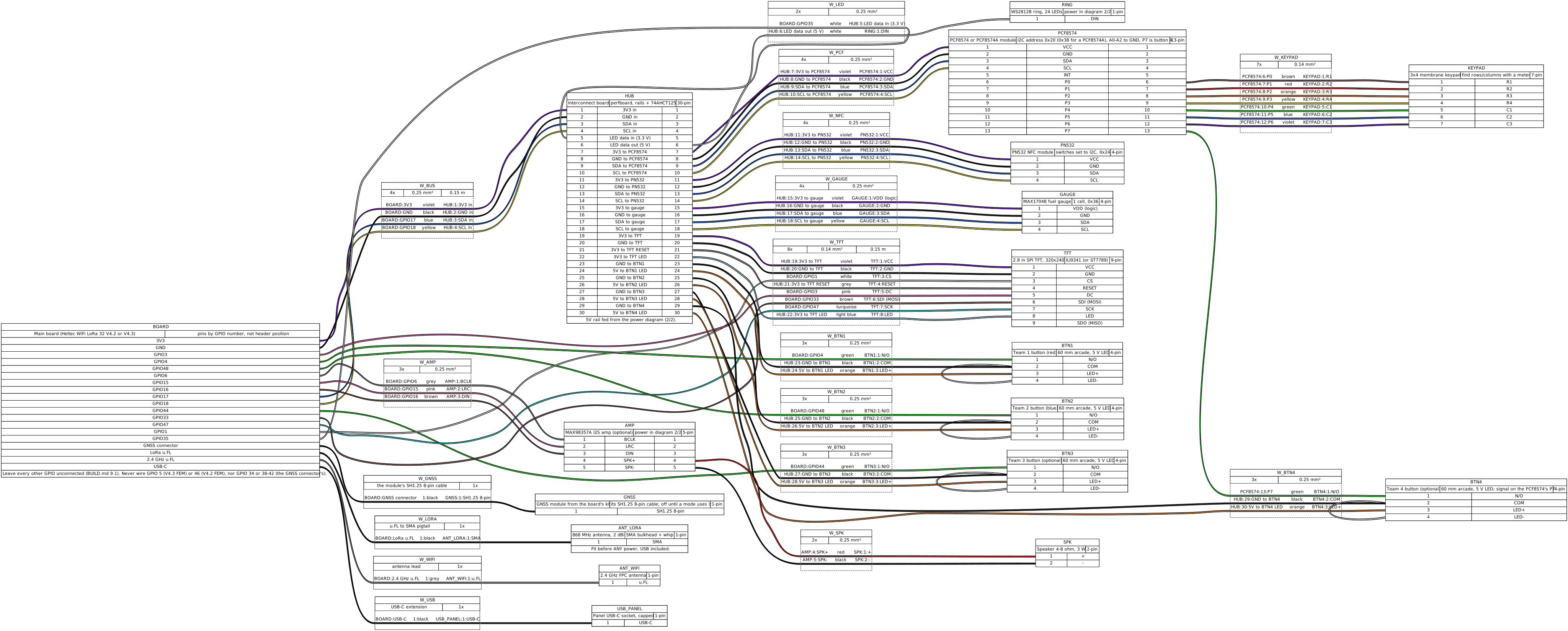

The drawing is very wide: tap or click it to open it at full size, where you can zoom and pan. It sits on a white sheet in the dark theme too, so the wire colours stay true.
Satellite
A small box for a secondary point or a beacon: the Field Box's board with two big team buttons (a third is possible), an LED ring that shows the team holding it, the board's own small screen, and one 18650 cell. About €30–40 in parts (the design's estimate). It runs the Field Box's own firmware with fewer parts fitted: the firmware reports each missing part once at start-up and carries on.
Without a keypad it cannot choose a game on its own: it plays the games a field controller invites it into, as a satellite or the master of Master and Satellites, or as a zone of any mode that needs only team buttons (Domination, Hold-All Domination, Last Stand). It joins a field by USB cable or by the pairing code on its small screen (it has no NFC reader for a field card).
Parts
- Heltec WiFi LoRa 32 V4 board, revision V4.2 or V4.3, 863–928 MHz, without its shell.
- An 868 MHz antenna of 2 dBi or less (the board kit's) and a 2.4 GHz antenna, which is required: the first setup, mode downloads and firmware updates use Wi-Fi.
- Two (or three) 60 mm arcade buttons with 5 V LEDs.
- A WS2812B LED ring (24 LEDs by default; 12 or 16 with one firmware setting), with the 74AHCT125 level shifter, a 330 Ω resistor and a 1000 µF capacitor, on a small perfboard.
- A MAX17048 battery gauge, recommended: without it the box never knows its battery level.
- One protected 18650 cell in a holder (or a 1S pack with a protection board), a 5 A fuse, a Schottky diode, a covered main switch, a 5 V boost converter for the ring, and lever splices: the Field Box's power path with one cell.
- Sound is optional: the Field Box's MAX98357A amplifier and a small speaker.
- A plastic IP65 box in a bright colour, with a vent and cable glands, and "GAME PROP" labels.
Pins
The firmware's defaults. Every board pin that is not in this table stays unconnected.
| What | GPIO |
|---|---|
| Team button 1 (the game's first team) | 4 |
| Team button 2 (the second team) | 48 |
| Team button 3, optional (the board's UART0 receive line) | 44 |
| LED ring data, through the 74AHCT125 level shifter | 35 |
| I2C SDA, for the battery gauge (the board's own bus) | 17 |
| I2C SCL | 18 |
| Amplifier BCLK (optional) | 6 |
| Amplifier LRC | 15 |
| Amplifier DIN | 16 |
The firmware still drives the Field Box's screen pins (GPIO 1, 3, 33 and 47): leave them unconnected.
Its wiring is a subset of the Field Box's: follow the Field Box's wiring diagrams and leave out the parts this build does not have (the colour screen, the keypad and the NFC reader). A drawing of its own does not exist yet.
Steps
- Read the chip next to the board's LoRa antenna connector: KCT8103L is a V4.3 (the firmware's default), GC1109 a V4.2. Fit and label both antennas before the board is ever powered.
- Plan the box on paper, then drill every hole before any electronics go in: buttons and ring on the lid, the switch recessed or covered, a vent low down.
- Build the power path without the board: cell, fuse, diode, switch, splices; set the boost converter to 5.0–5.2 V on its own before anything is connected to it.
- Build the small interconnect board: the 3V3, GND and 5V rails (and SDA and SCL for the gauge) and the level shifter, as in the Field Box's manual.
- Wire the buttons (to GND when pressed), the ring through the level shifter, the gauge and the optional amplifier, by the pins above.
- Check with the meter, the cell out: no short between the rails, each button only while pressed, the polarity of the board's battery lead.
- Build and flash the Field Box firmware as its manual says, set for your board revision and your ring's number of LEDs.
- Do the bring-up steps that apply to a Satellite: start-up, buttons, LEDs, battery, and the radio and its transmit power before any game.
- Set its name, region and admin PIN in its Wi-Fi setup page from a phone, adopt it into your field by USB cable or pairing code, and invite it into a game from the GM console.
Not decided yet
- The piezo buzzer of the original design: the firmware makes sound only through the amplifier, so a buzzer would need a firmware change.
- The enclosure: no box has been chosen yet.
- The runtime on one cell: not measured.
- A wiring diagram of its own: for now the Field Box's diagrams show every wire a Satellite has.
The full guide: Satellite build guide.
I/O pod
The box that lends an Android prop what a phone lacks: big team buttons, a keypad, an LED ring, sound, an NFC reader, a switch that tells when the box is opened, and a LoRa radio. The phone runs the game mode; the pod is its hands and its radio, over a USB cable or Bluetooth. It is the Field Box's hardware without the colour screen, running the pod firmware, which has been tested on a computer but not yet on a board. About €35 in parts (the design's estimate).
Every part but the board is optional: the pod tells the phone what it has, and the phone uses only that. Button 1 is the game's first team, as on a Field Box. An opened enclosure reaches the GM console as a tamper alert.
Parts
- The Field Box's parts, less the screen: the board, the buttons (up to four), the keypad and its PCF8574 expander, the LED ring with its level shifter, the PN532 NFC reader, the amplifier and speaker, the battery gauge, and the same one-cell power path.
- Both antennas: LoRa, and 2.4 GHz for Bluetooth.
- A microswitch that the closed lid holds pressed: the enclosure switch.
- A panel USB-C socket with data lines (not charge-only) for the phone's cable, and a USB-C OTG cable for the phone.
- On the bench only: a 3.3 V USB-serial adapter to read the pod's log.
Pins
The firmware's defaults. Every board pin that is not in this table stays unconnected.
| What | GPIO |
|---|---|
| Team button 1 (the game's first team) | 4 |
| Team button 2 (the second team) | 48 |
| Team button 3, optional (the board's UART0 receive line) | 44 |
| Team button 4 (on the keypad expander) | PCF8574 P7 |
| LED ring data, through the 74AHCT125 level shifter | 35 |
| I2C SDA, for the keypad expander, the NFC reader and the battery gauge (the board's own bus) | 17 |
| I2C SCL | 18 |
| Amplifier BCLK (optional) | 6 |
| Amplifier LRC | 15 |
| Amplifier DIN | 16 |
| Enclosure switch, to GND | 47 |
| Log output (UART0 TX): only a 3.3 V USB-serial adapter's RX, on the bench | 43 |
The pod does not use the Field Box's other screen pins (GPIO 1, 3 and 33): leave them unconnected.
The pod's wiring is the Field Box's without the screen: follow the Field Box's wiring diagrams and leave out the screen and its wires. A drawing of its own does not exist yet.
Steps
- Build it as a Field Box without the screen: board revision, antennas, enclosure, power path, interconnect board, then the keypad, ring, NFC reader, buttons and amplifier you fit, each with the manual's checks.
- Mount the microswitch so the closed lid presses it, and wire it from GPIO 47 to GND. The pod watches it only after it has read closed once, so a pod without one never raises an alarm.
- Build the pod firmware (
python tools/docker_fw.py pod) and flash it from thebuild-podfolder, as the Field Box's. - Read its log on GPIO 43 with the USB-serial adapter: the USB-C port carries the pod's link to the phone, not the log.
- In the app, link it over a USB-C OTG cable, then over Bluetooth (Android asks to pair once).
- Run the pod's bring-up checks, including the radio's transmit power before any game.
Not decided yet
- A separate siren or strobe: the pod's sound is its amplifier; switching other loads is not in its firmware.
- Power from the phone: on a cable, the phone powers the pod and may charge its cell. Whether it should, and how much a phone gives, are to be checked at the first build.
- The enclosure, and how the phone and the pod are carried together.
- Settings from the phone: button colours, the number of LEDs and the rest are set in the firmware build for now.
The full guide: I/O pod build guide, and the pod's checks with a phone in the bring-up list.
Radio modem
The controller's radio: a second Heltec WiFi LoRa 32 V4, flashed with the modem image and plugged into the field controller's USB port. Without it the controller runs and the console opens, but nothing reaches the boxes and nothing is heard from them. It has no Wi-Fi, so it needs only the LoRa antenna.
A modem flashed like this ran with the controller and real boxes on a bench (a computer, the controller in Docker). It has not run on a Raspberry Pi yet, not on macOS, and not on a field.
Steps
- Fit the LoRa antenna before the board has any power, also for flashing, and use a USB-C data cable. Decide the radio region: the modem and the boxes must share it.
- Download
atalaia-modem-<version>-usb.zipandSHA256SUMSfrom the releases (V4.3, EU868), or build it:python tools/docker_fw.py modem(V4.2, Taiwan, other antennas). - With esptool 4.8.1, erase a new board and write the files of
flash_args:esptool --chip esp32s3 -p PORT write_flash "@flash_args", with the portCOM5on Windows,/dev/ttyACM0on Linux,/dev/cu.usbmodem…on macOS. On Linux, join thedialoutgroup first. - The board's screen shows the tower and MODEM MODE, then
LINK waiting. That is a healthy modem that has no controller yet. RADIO FAULT means the radio chip did not start. - Plug it into the controller, find its port (
ls /dev/ttyACM*), put it in[modem] portof/etc/atalaia/controller.tomland restart the service (sudo systemctl restart atalaia-controller). - The screen says LINK OK, the console's header says Radio: up, and the controller's log has
modem link up. - Switch on an adopted box, create a game and invite the box: it goes sending, invited, joined, and the modem's screen counts packets.
Every command for each system, how to find the port, and a troubleshooting table (charge-only cable, wrong port, port held by another program, dialout, region mismatch, LINK waiting or DOWN, RADIO FAULT, wrong partition table): Set up the radio modem.
Target addon
Not buildable yet: the box's side of the port is decided, the addon itself is not. Do not wire a plate to a box from this page.
A plate that players shoot at, with a sensor that feels each hit. It plugs into a box and turns it into a scoring target for Target Windows, whose rules are built and tested in the simulator; the box's own ring of lights shows the window.
What is decided
- A steel or polycarbonate plate, a piezo sensor and a small processor of its own (RP2040 or ATtiny class) to detect hits. About €20–30 in parts (the design's estimate).
- It plugs into a waterproof 5-pin M12 connector on the box that carries 3.3 V only: the board's 3.3 V, ground and the two I2C lines; no 5 V, and the fifth pin stays free. Cables of up to 2 m. Its processor tells the box what it is, so the box needs no new driver per addon.
- It may take at most 25 mA from the box, through a resettable fuse: enough for its processor and sensor, not for lights. Target Windows lights the box's own LED ring; an addon with lights of its own needs a battery of its own.
- No interrupt line: the box reads the addon over I2C every 20 ms, about 3 % of the bus, so a hit reaches the game within about 21 ms. No pin of the box changes. The box's firmware already has this reading, tested, waiting for the addon.
- Game scripts see each hit with its strength (0 to 255), and can arm and disarm the target. The same is defined for a phone's I/O pod.
- Target Windows lights the target in a random team's colour for a few seconds; a hit strong enough in that window scores for that team.
- Then come the addon's own firmware, the box putting its reading of the port to use, and the sensor tuned on real steel and polycarbonate plates; Target Windows then becomes a mode a box offers.
Not decided yet
- The processor (RP2040 or ATtiny, within the 25 mA) and its firmware.
- The addon's I2C address and how it says what it is; how a hit is reported has a draft, final with the first addon.
- The checks of the first build: the bus's pull-up resistors with 2 m of cable, the fuse, and protecting the connector from static and water.
- The sensor circuit and its mounting, and the plate, its stand and its angle.
Safety, once there is something to build
- Eye and face protection for everyone within range while anyone shoots at it, at the bench too.
- BBs bounce off a hard plate, and some come back: angle a steel plate so they go down to the ground, never flat towards the shooter.
- Only the plate is a target: never shoot at the box, the cable or the connector, and keep the electronics behind the plate or in their own enclosure.
- The field's power limits apply to shooting at targets as at players.
What is decided, with the documents behind each decision: target addon guide.